SLVSCE1C August 2014 – November 2015 TPS25921A , TPS25921L
PRODUCTION DATA.
- 1 Features
- 2 Applications
- 3 Description
- 4 Application Schematic
- 5 Revision History
- 6 Pin Configuration and Functions
- 7 Specifications
- 8 Parametric Measurement Information
-
9 Detailed Description
- 9.1 Overview
- 9.2 Functional Block Diagram
- 9.3 Feature Description
- 9.4 Device Functional Modes
-
10Applications and Implementation
- 10.1 Application Information
- 10.2
Typical Application
- 10.2.1
Precision Current Limiting and Protection for White Goods
- 10.2.1.1 Design Requirements
- 10.2.1.2 Detailed Design Procedure
- 10.2.1.3 Application Curves
- 10.2.1
Precision Current Limiting and Protection for White Goods
- 10.3 System Examples
- 11Power Supply Recommendations
- 12Layout
- 13Device and Documentation Support
- 14Mechanical, Packaging, and Orderable Information
Package Options
Mechanical Data (Package|Pins)
- D|8
Thermal pad, mechanical data (Package|Pins)
Orderable Information
1 Features
- 4.5 V – 18 V Operating Voltage, 20 V (Max)
- 90 mΩ RDS(ON) (Typical)
- 0.4 A to 1.6 A Adjustable Current Limit
- ±2% Accurate ILIMIT at 1A at 25°C
- ±3% Overvoltage, Undervoltage Threshold
- Programmable dVO/dt Control
- Fault Output for Thermal Shutdown, UVLO and OVP
- -40°C to 125°C Junction Temperature Range
- Auto-Retry and Latch-Off Versions
- UL2367 Recognized - File No. E169910
- UL60950 - Safe during Single Point Failure Test
2 Applications
- White Goods, Appliances
- Set Top Boxes, DVD and Gaming Consoles
- HDD and SSD drives
- Smart Meters, Gas Analyzers
- Smart Load Switch
- USB Switch
- Adapter Power Devices
3 Description
The TPS25921 is a compact, feature rich eFuse with a full suite of protection functions. The wide operating voltage allows control of many popular DC buses. The precise ±2% current limit, at room temperature, provides excellent accuracy making the TPS25921 well suited for many system protection applications.
Load, source and device protection are provided with multiple programmable features including overcurrent, overvoltage and undervoltage. 3% threshold accuracy for UV and OV, ensures tight supervision of bus voltages, eliminating the need for supervisor circuitry. Fault flag output (FLT) is provided for system status monitoring and down stream load control.
For hot-plug-in boards, TPS25921 provides in-rush current control and programmable output ramp-rate. Output ramp rate is programmable using a capacitor at soft-start (SS) pin, for maximum design flexibility.
Device Information(1)
| PART NUMBER | PACKAGE | BODY SIZE (NOM) |
|---|---|---|
| TPS25921A | SOIC | 4.90mm x 3.91mm |
| TPS25921L |
- For all available packages, see the orderable addendum at the end of the datasheet.
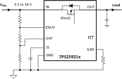
4 Application Schematic

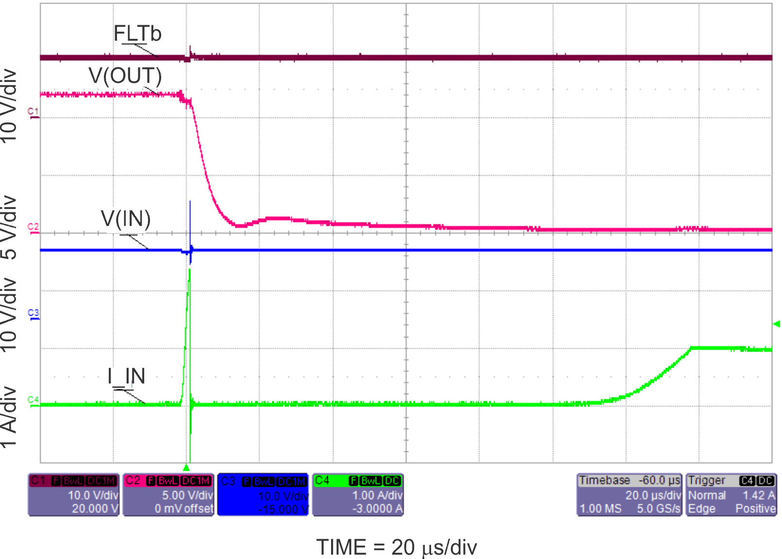
12V Short Circuit Response
