SLVSD95 November 2016 TPS25810-Q1
PRODUCTION DATA.
- 1 Features
- 2 Applications
- 3 Description
- 4 Revision History
- 5 Pin Configuration and Functions
- 6 Specifications
-
7 Detailed Description
- 7.1 Overview
- 7.2 Functional Block Diagram
- 7.3
Feature Description
- 7.3.1 Configuration Channel Pins CC1 and CC2
- 7.3.2 Current Capability Advertisement and Overload Protection
- 7.3.3
Undervoltage Lockout (UVLO)
- 7.3.3.1 Device Power Pins (IN1, IN2, AUX, OUT, and GND)
- 7.3.3.2 FAULT Response
- 7.3.3.3 Thermal Shutdown
- 7.3.3.4 REF
- 7.3.3.5 Audio Accessory Detection
- 7.3.3.6 Debug Accessory Detection
- 7.3.3.7 Plug Polarity Detection
- 7.3.3.8 Device Enable Control
- 7.3.3.9 Load Detect
- 7.3.3.10 Power Wake
- 7.3.3.11 Port Power Management (PPM)
- 7.3.3.12 Implementing PPM in a System With Two Type-C Ports
- 7.3.3.13 PPM Operation
- 7.4 Device Functional Modes
- 8 Application and Implementation
- 9 Power Supply Recommendations
- 10Layout
- 11Device and Documentation Support
- 12Mechanical, Packaging, and Orderable Information
Package Options
Refer to the PDF data sheet for device specific package drawings
Mechanical Data (Package|Pins)
- RVC|20
Thermal pad, mechanical data (Package|Pins)
- RVC|20
Orderable Information
1 Features
- USB Type-C Rev. 1.2 Compliant DFP Controller
- Connector Attach or Detach Detection
- STD, 1.5-A, or 3-A Capability Advertisement on CC
- Super-Speed Polarity Determination
- VBUS Application and Discharge
- VCONN Application to Electronically Marked Cable
- Audio and Debug Accessory Identification
- 0.7-µA (typ) IDDQ When Port Is Unattached
- Three Input Supply Options
- IN1: USB Charging Supply
- IN2: VCONN Supply
- AUX: Device Power Supply
- Power Wake Supports Low Power in System Hibernate (S4) and OFF (S5) Power States
- 34-mΩ (typ) High-Side MOSFET
- Programmable 1.7-A or 3.4-A ILIM (±7.1%)
- Port Power Management Enables Power Resource Optimization Across Multiple Ports
- Package: 20-Pin WQFN (3 x 4) (1)
2 Applications
- Automotive Infotainment Systems
- Automotive Back-seat USB Charging
3 Description
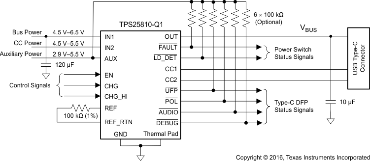
The TPS25810-Q1 device is a USB Type-C downstream-facing port (DFP) controller with an integrated 3-A rated USB power switch. The TPS25810-Q1 device monitors the Type-C configuration channel (CC) lines to determine when a USB device is attached. If an upstream-facing port (UFP) device is attached, the TPS25810-Q1 device applies power to VBUS and communicates the selectable VBUS current-sourcing capability to the UFP via the pass-through CC line. If the UFP is attached using an electronically marked cable, the TPS25810‑Q1 device also applies VCONN power to the cable CC pin. The TPS25810-Q1 device also identifies when Type-C audio or debug accessories are attached.
The TPS25810-Q1 device draws less than 0.7 µA (typ) when no device is attached. Additional system power saving is achievable in the S4 and S5 system power states by using the UFP output to disable the high-power 5-V supply when no UFP is attached. In this mode, the device is capable of running from an auxiliary supply (AUX), which can be a lower-voltage supply (3.3 V), typically powering the system µC in low-power states (S4 and S5).
The TPS25810-Q1 34-mΩ power switch has two selectable fixed-current limits that align with the Type‑C current levels. The FAULT output signals when the switch is in an overcurrent or overtemperature condition. The LD_DET output controls power management to multiple high-current Type-C ports in an environment where all ports cannot simultaneously provide high current (3 A).
Device Information(1)
| PART NUMBER | PACKAGE | BODY SIZE (NOM) |
|---|---|---|
| TPS25810-Q1 | WQFN (20) | 3.00 mm x 4.00 mm |
- For all available packages, see the orderable addendum at the end of the data sheet.
Simplified Schematic
