SBAS704B June 2015 – October 2015 OPT8241
PRODUCTION DATA.
- 1 Features
- 2 Applications
- 3 Description
- 4 Revision History
- 5 Pin Configuration and Functions
- 6 Specifications
- 7 Detailed Description
- 8 Application and Implementation
- 9 Power Supply Recommendations
- 10Layout
- 11Device and Documentation Support
- 12Mechanical, Packaging, and Orderable Information
Package Options
Mechanical Data (Package|Pins)
- NBN|78
Thermal pad, mechanical data (Package|Pins)
Orderable Information
1 Features
- Imaging Array:
- 320 × 240 Array
- 1/3” Optical Format
- Pixel Pitch: 15 µm
- Up to 150 Frames per Second
- Optical Properties:
- Responsivity: 0.35 A/W at 850 nm
- Demodulation Contrast: 45% at 50 MHz
- Demodulation Frequency: 10 MHz to 100 MHz
- Output Data Format:
- 12-Bit Phase Correlation Data
- 4-Bit Common-Mode (Ambient)
- Chipset Interface:
- Compatible with TI's Time-of-Flight Controller OPT9221
- Sensor Output Interface:
- CMOS Data Interface (50-MHz DDR, 16-Lane Data, Clock and Frame Markers)
- LVDS:
- 600 Mbps, 3 Data Pairs
- 1-LVDS Bit Clock Pair, 1-LVDS Sample Clock Pair
- Timing Generator (TG):
- Addressing Engine with Programmable Region of Interest (ROI)
- Modulation Control
- De-Aliasing
- Master, Slave Sync Operation
- I2C Slave Interface for Control
- Power Supply:
- 3.3-V I/O, Analog
- 1.8-V Analog, Digital, I/O
- 1.5-V Demodulation (Typical)
- Optimized Optical Package (COG-78):
- 8.757 mm × 7.859 mm × 0.7 mm
- Integrated Optical Band-Pass Filter
(830 nm to 867 nm) - Optical Fiducials for Easy Alignment
- Operating Temperature: 0°C to 70°C
2 Applications
- Depth Sensing:
- Location and Proximity Sensing
- 3D Scanning
- 3D Machine Vision
- Security and Surveillance
- Gesture Controls
- Augmented and Virtual Reality
3 Description
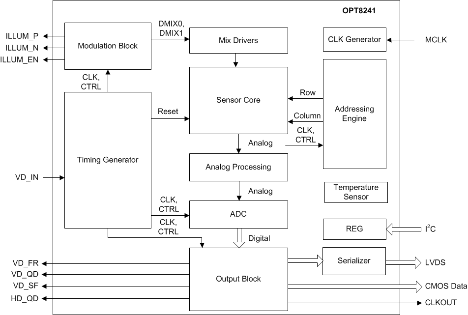
The OPT8241 time-of-flight (ToF) sensor is part of the TI 3D ToF image sensor family. The device combines ToF sensing with an optimally-designed analog-to-digital converter (ADC) and a versatile, programmable timing generator (TG). The device offers quarter video graphics array (QVGA 320 x 240) resolution data at frame rates up to 150 frames per second (600 readouts per second).
The built-in TG controls the reset, modulation, readout, and digitization sequence. The programmability of the TG offers flexibility to optimize for various depth-sensing performance metrics (such as power, motion robustness, signal-to-noise ratio, and ambient cancellation).
Device Information(1)
| PART NUMBER | PACKAGE | BODY SIZE (NOM) |
|---|---|---|
| OPT8241 | COG (78) | 7.859 mm × 8.757 mm |
- For all available packages, see the package option addendum at the end of the data sheet.
Block Diagram

4 Revision History
Changes from A Revision (June 2015) to B Revision
- Changed equations to correct format throughout document Go
- Changed name of Function column in Pin Functions table Go
- Changed SCL and SDATA pin descriptions in Pin Functions table Go
- Added parameter names to Sensor section of Electrical Characteristics table Go
- Changed depth resolution description in Table 5 Go
Changes from * Revision (June 2015) to A Revision
- Released to productionGo