SNOSC70C April 2012 – July 2016 LMV601 , LMV602 , LMV604
PRODUCTION DATA.
- 1 Features
- 2 Applications
- 3 Description
- 4 Revision History
- 5 Pin Configuration and Functions
-
6 Specifications
- 6.1 Absolute Maximum Ratings
- 6.2 ESD Ratings
- 6.3 Recommended Operating Conditions
- 6.4 Thermal Information
- 6.5 Electrical Characteristics - DC (2.7 V)
- 6.6 Electrical Characteristics - AC (2.7 V)
- 6.7 Electrical Characteristics - DC (5 V)
- 6.8 Electrical Characteristics - AC (5 V)
- 6.9 Typical Characteristics
- 7 Detailed Description
- 8 Application and Implementation
- 9 Power Supply Recommendations
- 10Layout
- 11Device and Documentation Support
- 12Mechanical, Packaging, and Orderable Information
Package Options
Mechanical Data (Package|Pins)
Thermal pad, mechanical data (Package|Pins)
Orderable Information
1 Features
- Typical 2.7-V Supply Values; Unless Otherwise Noted
- Ensured 2.7-V and 5-V Specifications
- Supply Current (Per Amplifier): 100 µA
- Gain Bandwidth Product: 1 MHz
- Shutdown Current (LMV601): 45 pA
- Turnon Time from Shutdown (LMV601): 5 µs
- Input Bias Current: 20 fA
2 Applications
- Cordless and Cellular Phones
- Laptops
- PDAs
- PCMCIA and Audio
- Portable and Battery-Powered Electronic Equipment
- Supply Current Monitoring
- Battery Monitoring
- Buffers
- Filters
- Drivers
3 Description
The LMV60x devices are single, dual, and quad low-voltage, low-power operational amplifiers. They are designed specifically for low-voltage, general-purpose applications. Other important product characteristics are low input bias current, rail-to-rail output, and wide temperature range. The LMV60x have 29-nV voltage noise at 10 KHz, 1-MHz GBW, 1-V/µs slew rate, 0.25-mV Vos. The LMV60x operates from a single supply voltage as low as 2.7 V, while drawing 100-µA (typical) quiescent current. In shutdown mode, the current can be reduced to 45 pA.
The industrial-plus temperature range of −40°C to 125°C allows the LMV60x to accommodate a broad range of extended environment applications.
The LMV601 offers a shutdown pin that can be used to disable the device. Once in shutdown mode, the supply current is reduced to 45 pA (typical).
The LMV601 is offered in the tiny 6-pin SC70 package, the LMV602 in space-saving 8-pin VSSOP and SOIC, and the LMV604 in 14-pin TSSOP and SOIC. These small package amplifiers offer an ideal solution for applications requiring minimum PCB footprint. Applications with area constrained printed-circuit board requirements include portable and battery-operated electronics.
Device Information(1)
| PART NUMBER | PACKAGE | BODY SIZE (NOM) |
|---|---|---|
| LMV601 | SC70 (6) | 2.00 mm × 1.25 mm |
| LMV602 | SOIC (8) | 4.90 mm × 3.91 mm |
| VSSOP (8) | 3.00 mm × 3.00 mm | |
| LMV604 | SOIC (8) | 4.90 mm × 3.91 mm |
| TSSOP (14) | 5.00 mm × 4.40 mm |
- For all available packages, see the orderable addendum at the end of the data sheet.
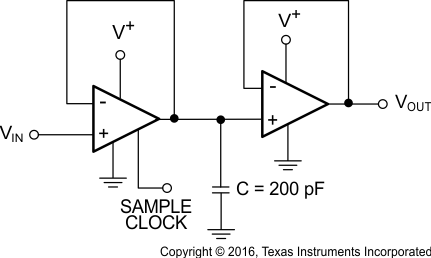
Sample and Hold Circuit
