SNVS052E September 1999 – April 2016 LM809 , LM810
PRODUCTION DATA.
- 1 Features
- 2 Applications
- 3 Description
- 4 Revision History
- 5 Pin Configuration and Functions
- 6 Specifications
- 7 Detailed Description
- 8 Application and Implementation
- 9 Power Supply Recommendations
- 10Layout
- 11Device and Documentation Support
- 12Mechanical, Packaging, and Orderable Information
Package Options
Mechanical Data (Package|Pins)
- DBZ|3
Thermal pad, mechanical data (Package|Pins)
Orderable Information
1 Features
- Precision Monitoring of Supply Voltages
- Available Threshold Options:
2.63 V, 2.93 V, 3.08 V, 4.38 V, 4.63 V
- Available Threshold Options:
- Superior Upgrade to MAX809 and MAX810
- Fully Specified Over Temperature
- 140-ms Minimum Power-On Reset Pulse Width, 240-ms Typical
- Active-Low RESET Output (LM809)
- Active-High RESET Output (LM810)
- Ensured RESET Output Valid for VCC ≥ 1 V
- Low Supply Current, 15-µA Typical
- Power Supply Transient Immunity
2 Applications
- Factory Automation
- Building Automation
- Programmable Logic Control
- Renewable Energy
- Microprocessor Systems
- Computers
- Controllers
- Intelligent Instruments
- Portable/Battery-Powered Equipment
- Automotive
3 Description
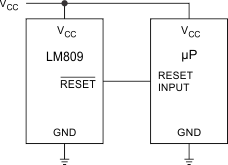
The LM809 and LM810 microprocessors supervisory circuits can be used to monitor the power supplies in microprocessor and digital systems. They provide a reset to the microprocessor during power-up, power-down and brown-out conditions.
The function of the LM809 and LM810 are to monitor the VCC supply voltage, and assert a reset signal whenever this voltage declines below the factory-programmed reset threshold. The reset signal remains asserted for 240 ms after VCC rises above the threshold. The LM809 has an active-low RESET output, while the LM810 has an active-high RESET output.
Seven standard reset voltage options are available, suitable for monitoring 5-V, 3.3-V, and 3-V supply voltages.
With a low supply current of only 15 µA, the LM809 and LM810 are ideal for use in portable equipment.
Device Information(1)
| PART NUMBER | PACKAGE | BODY SIZE (NOM) |
|---|---|---|
| LM809, LM810 | SOT-23 (3) | 2.92 mm × 1.30 mm |
- For all available packages, see the orderable addendum at the end of the data sheet.
Typical Application for Microprocessor Reset Circuit
