SLLA584 March 2022 ISO1640 , ISO1641 , ISO1642 , ISO1643 , ISO1644
1 Application Brief
Reliable and cost-effective integrated circuit (IC) solutions used for isolation are a critical part of board to board communication within industrial and automotive designs. There are several isolated intra-board interfaces to choose from, each with their own benefits. A standard I2C interface consists of a two-wire interface, with a bi-directional serial data (SDA) line and an, either bidirectional or unidirectional, serial clock line (SCL). The Inter-Integrated Circuit (I2C) standard allows for a multi-device shared communication method between controllers and ICs such as data converters or sensors using only two lines. The I2C protocol typically runs at a slower speed, commonly 100kHz or 400kHz and up to 1MHz, allowing time for handshaking between the devices in a communication network. Adding isolation to I2C, such as in ISO1640 and ISO1641 devices, can break long distance ground loops, provide protection to human operators, and prevent damage to high voltage systems. Although I2C is a dependable communication standard, due to the aforementioned speed limitations, it is not the protocol of choice for time sensitive interrupts in some use cases and systems.
Opposed to I2C, Serial Peripheral Interphase (SPI) uses 4-channels to communicate between devices and runs at much faster speeds. SPI does not utilize bidirectional lines or an address scheme to talk to multiple devices in a network. Instead, individual Chip Select (/CS) lines are used to note which device is being communicated to on the bus. With this architecture, SPI can run at much higher speeds, in some cases reach well over 40Mbps. As more devices are added to the communication bus, Individual Chip Select (/CS) lines are added. Since individual /CS lines are needed for devices added to the bus, I2C buses have the benefit of communicating with a large number of devices in a single communication bus without having to increase the number of lines used. In an isolated system, this would require increasing isolation channels needed for each /CS line. Because both SPI and I2C have their own benefits, many system designs incorporate both a SPI and I2C bus in the same module. This allows for systems to both minimize the number of isolated lines used with I2C and have an isolated solution for time sensitive signals with SPI.
To accommodate both faster signal
communication and slower bidirectional I2C communication in an isolated system, a
multiple-chip solution has historically been used. Texas Instruments latest digital
isolator family, ISO67xx, offers 2, 3, 4, and 6
unidirectional channel options for isolating UART, SPI, and GPIO. To have these
devices used in an I2C interface, the design would require multiple discrete
components (How to Isolate Signal and Power for I2C).
To simplify the use of SPI and I2C in the same device and package, Texas Instruments
released the ISO1642, ISO1643, and ISO1644 to help decrease board surface area while
providing quality isolation protection. Our new ISO164x family offers two
bidirectional I2C channels, and up to three unidirectional options with varying
directions in a single package. This allows designs to get smaller without
sacrificing features and the design flexibility of having multiple isolated
communication buses.
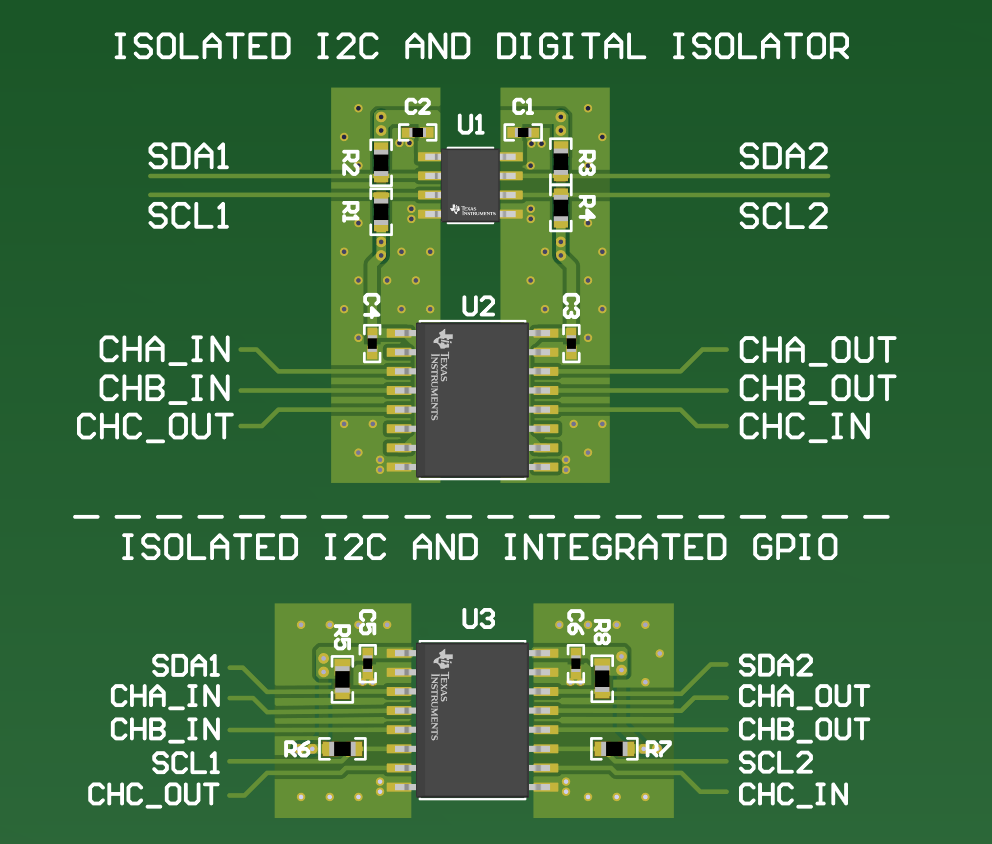
Figure 1-1 shows the difference in board area savings going from a multiple chip solution
solving I2C and SPI to a single ISO1644.
 Figure 1-1 I2C Footprint of Discrete I2C and Digital Isolator Circuit vs. ISO1644
Isolator Circuit
Figure 1-1 I2C Footprint of Discrete I2C and Digital Isolator Circuit vs. ISO1644
Isolator CircuitThe ISO1642/3/4 devices also make an excellent solution when only an isolated I2C bus is present in a system. Because, I2C runs at lower speeds, some designs may have time sensitive signals, such as a reset or power down signal, that cannot wait for a device to decode an I2C command to perform a function. GPIO lines are used parallel to the I2C bus to handle these signals and need to be isolated. The historical solution has been to add a separate digital isolator or optocoupler isolator to pass the additional lines across the barrier. The release of the new ISO1642/3/4 allows a design to address 2 or 3 GPIO lines, in parallel with the I2C device, without adding to the IC count or increasing the circuit board size. This one chip solution will not only decrease the surface area by 50% on you board, but will provide a cost-efficient solution depending on the amount of GPIO channels you need for your system.
There are multiple solutions that can accomplish intra-board communication, and the appropriate choice between interfaces is sometimes dependent on speed, size, or time sensitive signal reliability. Using a combination of Isolated SPI and Isolated I2C buses yields the most space reduction while also providing fast and reliable data. TI has designed an Isolated I2C family with GPIO integration to meet this need. These new generation of Isolated I2Cs found in the ISO164x family, allow for a wider array of use cases, and provide a fast, reliable, and size conscious solution to these needs.