SLLA522A August 2020 – May 2021 ISO1640 , ISO1641 , ISO6720-Q1 , ISO6721 , ISO6721-Q1 , ISO6731 , ISO6740 , ISO6741 , ISO6741-Q1 , ISO6742 , ISO7142CC-Q1 , ISO721-Q1 , ISO722-Q1 , ISO7220A-Q1 , ISO7221A-Q1 , ISO7221C-Q1 , ISO7231C-Q1 , ISO7240CF-Q1 , ISO7241C-Q1 , ISO7242C-Q1 , ISO7310-Q1 , ISO7320-Q1 , ISO7321-Q1 , ISO7330-Q1 , ISO7331-Q1 , ISO7340-Q1 , ISO7341-Q1 , ISO7342-Q1 , ISO7421A-Q1 , ISO7421E-Q1 , ISO7710-Q1 , ISO7720-Q1 , ISO7721-Q1 , ISO7730-Q1 , ISO7731-Q1 , ISO7740-Q1 , ISO7741-Q1 , ISO7741E-Q1 , ISO7742-Q1 , ISO7760-Q1 , ISO7761-Q1 , ISO7762-Q1 , ISO7763-Q1 , ISOW7841A-Q1
Tech Note
Serial communication interfaces are commonly used to transmit and receive data between two devices in industrial or automotive systems. Common interface types used in short distance, intra-board communication are UART, SPI, and I2C. Isolating these types of digital interfaces has historically been achieved using optocouplers, also known as optoisolators, despite their weak isolation performance, poor timing specifications, and limited temperature range. Optocouplers only remain a popular option when isolating digital interfaces due to their low cost. However, digital isolators can now provide a cost-competitive, easy-to-implement, and higher-performance solution, all in a small form factor. This article compares common optocoupler circuits to digital isolator circuits used to isolate common digital interfaces and demonstrate the overall benefits of a digital isolator solution. For more about the advantages of digital isolators compared to optocouplers, see Improve Your System Performance by Replacing Optocouplers with Digital Isolators.
UART
Universal Asynchronous Receiver and Transmitter (UART) is a very simple two-wire serial interface that allows for low-speed communication between two devices. The two push-pull, unidirectional lines are Receive (RX) and Transmit (TX). The interface works without a clock, so the receiver determines the bit rate automatically by sampling the period of positive voltage pulses. The automatic bit rate detection limits the max bit rate achieved with UART, making data rates over 100 kbps extremely rare.
Only two channels need to be isolated for UART and the low speeds make a straightforward and low-cost solution most desirable. Figure 1-1 shows a UART interface isolated using an optocoupler circuit and an equivalent circuit using ISO6721, TI's digital isolator solution targeted for cost-sensitive applications.
A UART interface is commonly configured with a standard diode input and open collector output optocoupler. Additional circuitry is needed with optocouplers, which adds board space and contributes to additional power consumption. On the input side of the optocoupler, a series resistor, Ri, is required to be connected to the anode to limit the current that flows across the diode. Due to aging, the current transfer ratio (CTR) of optocouplers degrades. To maintain the same level of performance throughout the lifetime of the system, designers have to overdesign by selecting a high Ri, which burns extra current.
The open collector output requires a pull-up resistor, RL, to create the logic high state. The value of RL is selected to minimize power consumption while also maintaining desired timing specs. Selecting a high RL value is important to ensure that the output of the optocoupler has the maximum voltage swing to meet a proper logic high state and maintain robust signal integrity. Conversely, increasing this value reduces the speed at which the optocoupler can respond to fast voltage changes due to a high resistance load and the high junction capacitance of the phototransistor. This ultimately limits the overall speeds that a designer could implement for UART.
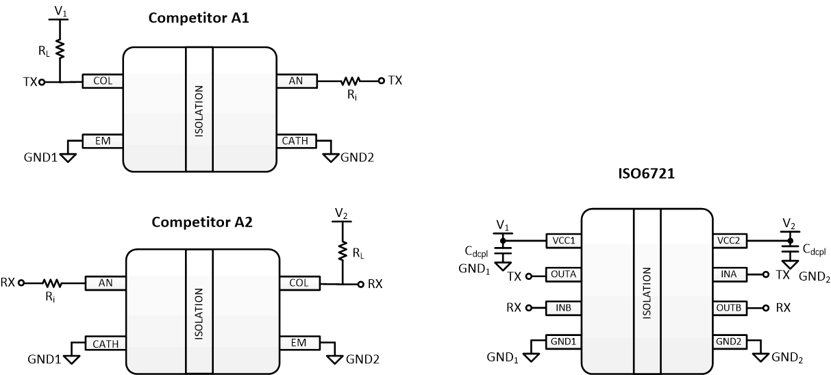 Figure 1-1 UART Optocoupler Circuit vs
ISO6721 Digital Isolator Circuit
Figure 1-1 UART Optocoupler Circuit vs
ISO6721 Digital Isolator CircuitThe ISO6721 digital isolator consumes five to 10 times less current than an optocoupler solution. The difference in total current consumption between the two circuits is shown in Table 1-1. Additionally, ISO6721 provides very tight channel-to-channel timing specifications and a smaller solution size due to its lack of additional passive components. The optocoupler circuit footprint is roughly two times the size (7 mm × 7.4 mm) as a single digital isolator (6 mm x 4.9 mm). The ease-of-use of the ISO6721 digital isolator circuit makes it a better solution to a widely used and simple digital interface.
| Competitor A | ISO6721 | |
|---|---|---|
| Primary Side Current | 10 mA | 1.45 mA |
| Secondary Side Current | 2 mA | 1.45 mA |
| Total Current | 12 mA/ch | 1.45 mA/ch |
SPI
The Serial Peripheral Interface (SPI) is a CMOS logic serial interface that requires four unidirectional data lines. The benefit of SPI is its higher speed where bit rates commonly exceed 1 Mbps and in some cases, reach as high as 30 Mbps. SPI is able to meet high speeds due to its push-pull output implementation allowing for fast switching, separate transmit and receive lines enabling full duplex communication, and a shared interface clock that automatically synchronizes bit boundaries between the parties. SPI is a “main-secondary” interface, meaning only one device on the bus controls when communication is allowed to occur.
Four channels are required to isolate the SPI interface. The four typical SPI interface lines are SCLK, CS, MOSI, and MISO. There are two types of high-speed optocouplers that can be used with SPI: open collector output and totem-pole output. These types of optocouplers only integrate up to two channels, which means two to four optocouplers have to be used together to isolate all four SPI channels.
Using a high-speed open collector output, as shown in Figure 1-2, also requires a series resistor, Ri, and, in this case, the combination of the resistor and the input shunt capacitance of the optocoupler creates a low-pass filter. The low-pass filter limits the maximum bit rate and overall SPI throughput.
To mitigate this effect, a capacitor, Cpeak, is placed across the resistor, Ri, to sharpen the edges of the bitstream. Optocouplers that have an open collector output will require a pull-up resistor, RL, to create the logic high state. The value RL poses a challenge since a high resistor value limits achievable bit rate but lowers power consumed by the circuit stage.
Along with high-speed optocouplers with open collector output, there are also offerings with push-pull outputs. For the high-speed totem-pole output optocoupler, the input is configured the same way as the open collector, but the output is a push-pull configuration and the pull-up resistor is not required. An output inversion is accomplished inside the optocoupler for this topology.
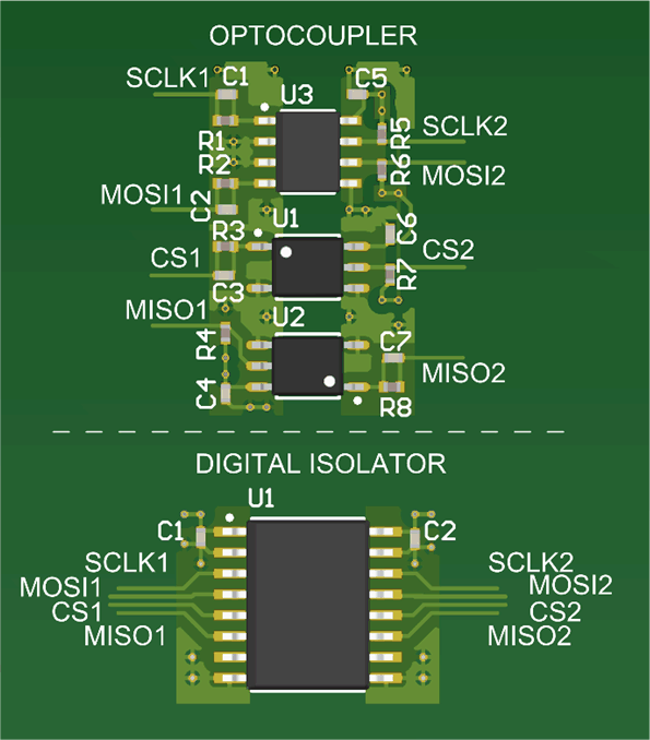 Figure 1-2 SPI Footprint of Optocoupler
Circuit vs ISO6741 Digital Isolator Circuit
Figure 1-2 SPI Footprint of Optocoupler
Circuit vs ISO6741 Digital Isolator CircuitGiven that an SPI interface is targeted for fast data transfer, it is critical that the isolation system supports 20 Mbps or 10 MHz frequency to meet industry speed requirements. It is a common misinterpretation that the data speed of the SPI interface is limited by the isolator speed, when in fact it is the propagation delay that limits the speed. The round trip delay of the clock to data path will set the limit of the maximum speed of the interface.
Figure 1-3 shows the relationship of a SCLK signal going through an isolator and the MISO responding and receiving data back. In the figure, the blue clock signal from the SOC gets delayed by the isolator propagation delay at the MCU. When the MCU responds and sends data back to the SOC, the receive data experiences a second delay through the isolator. Therefore, the total delay between the initial clock edge and the receive data is approximately twice the isolator propagation delay: 2 × tPROP < ½ tSCLK.
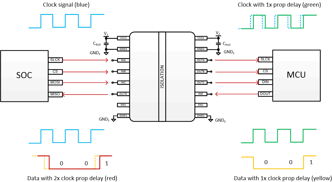 Figure 1-3 Digital Isolator Propagation
Delay for SPI Loop Timing
Figure 1-3 Digital Isolator Propagation
Delay for SPI Loop TimingTo meet 10 MHz, a maximum prop delay of 25 ns needs to be met. Optocouplers typically require a small RL of 350-Ω to meet fast timing specs and are commonly limited to a SPI clock rate of 7 MHz, without taking into account additional margin. The small RL causes more power to be consumed on the output of the optocoupler. There are a variety of optocoupler solutions in the market but there is a strong tradeoff between high power consumption and tighter timing.
Figure 1-2 shows how SPI can be isolated with only one ISO6741 device versus two high-speed optocouplers with additional passive components. The board footprint of the optocoupler circuit is 12 mm × 21.5 mm versus the ISO6741 digital isolator footprint, which is only 16 mm x 12 mm. The ISO6741 has CMOS inputs and push-pull outputs that eliminates the need for all of the passive components in the data path. The power consumption comparison is also noted in Table 1-2. Selecting an isolator that has robust timing specs to meet fast data rates while consuming low power is key for a more sophisticated digital interface solution like SPI.
| Competitor A (open-collector) |
Competitor B (totem-pole) |
ISO6741 | |
|---|---|---|---|
| Primary Side Current | 10 mA | 2 mA | 1.27 mA |
| Secondary Side Current | 14 mA | 2 mA | 1.12 mA |
| Total Current | 24 mA/ch | 3 mA/ch | 2.4 mA/ch |
I2C
The Inter-Integrated Circuit (I2C) interface is a two-wire serial interface that efficiently allows multiple devices to be connected on the same bus. The I2C bus consists of two lines: a bidirectional serial data line (SDA) and a serial clock line (SCL) that can either be unidirectional or bidirectional depending on the design. The output structure of the bus lines are open collector to allow for easy sharing of the bus. The I2C bidirectional channels provide a unique challenge for isolation. The isolation channel must support bidirectional data transfer and the circuit must ensure that it does not drive its own line while it is being driven by the transmitter.
Historically, isolating I2C was accomplished with optocouplers and discrete logic to control the data direction on the lines. The discrete components are required to avoid bus glitches and any latch up conditions on the bidirectional lines. Without the discrete components, the design runs the risk of having a condition on the line where the left side is driving the signal line low to the right and then, in turn, the right side drives the signal low back to the left. This would create a latch up condition where the bidirectional lines could never be released to return high. Figure 1-4 shows an I2C isolation circuit using optocouplers capable of reaching speeds up to 400 kbps. For the sake of simplicity, this I2C diagram shows a “main-secondary” implementation where SCL is a unidirectional signal only. Two optocoupler devices are required: one to transmit SCL and SDA, and one to receive SDA.
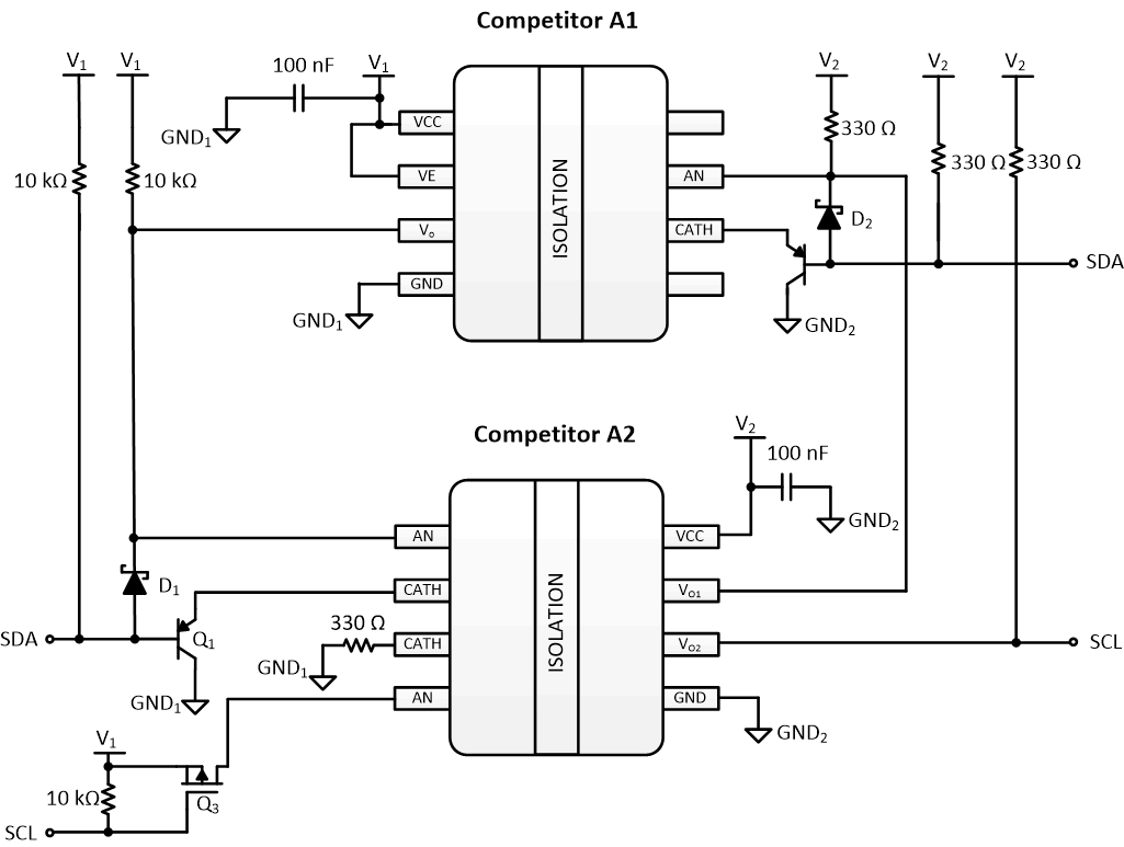 Figure 1-4 I2C Optocoupler Circuit
 In addition to the pull-up resistors required for the I2C interface, the circuit requires transistors, Q1 and Q2, and diodes, D1 and D2, to create an open collector output and to avoid bus contention on the bidirectional line. The 330-Ω pull-up resistor values are used to provide higher input current to the optocoupler input to meet required turn on times.
More modern designs with digital isolators utilize integration of the external components to provide a smaller and simpler solution. Figure 1-5 shows the layout of a solution using optocouplers compared to TI's single chip ISO1641 with unidirectional clock and bidirectional data. The ISO1641 has integrated the internal circuitry required to prevent SDA from being simultaneously driven by both sides of the isolator. The ISO1640 and ISO1641 have integrated the internal circuitry on both the SDA and SCL line to enable bidirectional control on the SCL line for I2C clock stretching if the design requires. The solution is very simple with SDA and SCL being the only single bidirectional data pins on either side of the isolation boundary. Furthermore, the inputs are buffered, reducing the current consumption of the solution and eliminating the need for the LED current limiting resistors. The ISO1640 and ISO1641 significantly reduces the size and complexity of the circuit compared to the optocoupler solution.
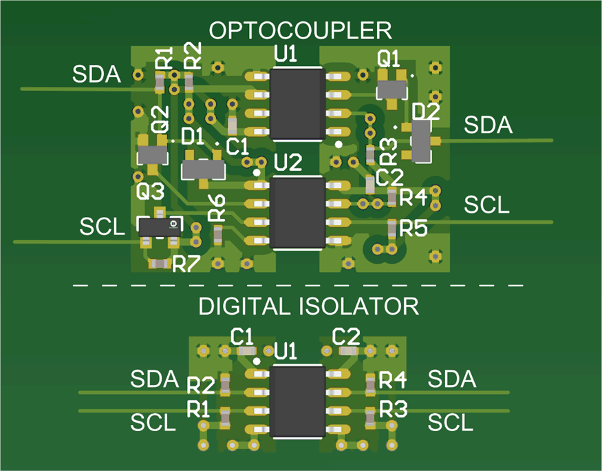 Figure 1-5 I2C Footprint of Optocoupler
Circuit vs ISO1641 Isolator Circuit
Figure 1-5 I2C Footprint of Optocoupler
Circuit vs ISO1641 Isolator CircuitWhile existing optocoupler based designs may have required as many as 16 discrete components, TI's I2C isolator solution can be used with as few as six components in a very small footprint while simplifying signal routing. The only discrete components required along with the single ISO1640 and ISO1641 are pullup resistors, for the open collector I2C bus lines, and decoupling capacitors for the digital isolator power supply pins. Reducing this component count to a single digital isolator with a few passive components allows a design to save as much as three times the circuit board space. As Figure 1-5 shows, the optocoupler circuit is 22 mm x 15.5 mm versus the ISO1641 isolator footprint, which is only 15 mm x 8 mm.
A few primary reasons why an I2C interface is attractive to a design is its small size and simplicity of only two wires. The complexity around an optocoupler-based isolated I2C solution requiring discrete components weakens the value of why to use the interface to begin with. Using a digital isolator solution, like the ISO1640 and ISO1641, allows the designer to bring back the compact value of the I2C interface into an isolated solution.
Conclusion
TI’s digital isolators provide significant benefits compared to traditional optocoupler circuits for isolating digital interfaces while being cost competitive. In the case of UART, the ISO6721 provides a smaller footprint and much lower power consumption compared to its optocoupler equivalent. For SPI, The ISO6741 solution supports higher clock rates beyond 10 MHz, lower power per channel, and is significantly lower cost per channel than the totem-pole implementation. The large optocoupler footprint around an isolated I2C design becomes unattractive as systems become smaller. The ISO164x family of I2C interface isolators presents a simple and small solution with a native capability to achieve the higher I2C speeds. TI’s digital isolators produce a smaller PCB footprint due to channel consolidation and reduced number of passive components, in addition to providing robust isolation, timing specs, and EMC performance. They also yield circuit diagrams which are simpler to build and debug compared to their optocoupler equivalents.