SBOA162D May 2018 – March 2022 INA200 , INA200-Q1 , INA201 , INA201-Q1 , INA202 , INA202-Q1 , INA203 , INA203-Q1 , INA204 , INA205 , INA206 , INA207 , INA208 , INA300 , INA300-Q1 , INA301 , INA301-Q1 , INA302 , INA302-Q1 , INA303 , INA303-Q1 , INA381 , INA381-Q1
1 Application Brief
The amount of current flowing throughout a system provides insight in determining how effectively the system is operating. A basic insight into the system's operation is a comparison between the current being pulled from a power supply and a pre-defined target range for that particular operating condition. Current levels exceeding the expected current level indicate that an element in the system is consuming more power than expected. Likewise, if the current is lower than expected it may indicate some part of the system is not powered correctly or possibly disconnected.
There are multiple methods available to diagnose fault conditions in a system depending on how the out-of-range indication is intended to be used. One method is to monitor an entire system's current consumption to identify potentially damaging excursions for the power supply. In this case, measurement accuracy is typically not critical and requires a simple alert to indicate an out-of-range condition.
Fuses are commonly used for short-circuit protection preventing damaging levels of current from flowing in the system. In an out-of-range event the fuse will blow and break the circuit path. The fuse must be replaced for the system to operate correctly again. In worst case situations the system requires delivery to a repair facility if the fuse is not easily accessible.
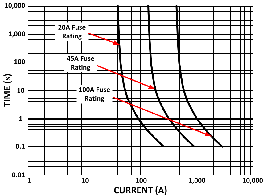
There is a time-current dependency that limits the effectiveness of a fuse in responding to a specific current threshold. An example time-current response of a fuse is shown in Figure 1-1.
 Figure 1-1 Typical Time-Current Fuse
Curve
Figure 1-1 Typical Time-Current Fuse
CurveAnother overcurrent protection scheme becoming more common is to allow the system to protect itself when an excursion is detected but then enable the system to return to normal operation once the fault condition has been cleared. This protection method uses a comparator comparing the monitored operating current levels to defined thresholds, looking for out-of-range conditions. Creating the necessary level of detection for a particular application relies on system specific variables such as the adjustability of the desired over-range threshold, the amount of margin acceptable in the threshold level and how quickly the excursion must be detected.
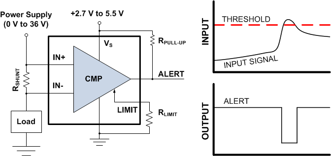
The INA300 is a specialized current sensing comparator with the ability to perform the basic comparison to expected operating thresholds required for out-of-range detection.
 Figure 1-2 INA300 Over-Current
Comparator
Figure 1-2 INA300 Over-Current
ComparatorFigure 1-2 shows the INA300 measuring the differential voltage developed across a current sensing resistor and the comparison to a user-adjustable threshold level. The alert output is pulled low when the threshold level is exceeded. The INA300’s alert response is issued following a current excursion in as short as 10µs.
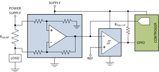
There may also be a need to provide information on how much current is actually being pulled by the supply or a particular load in addition to the fault indication. For these requirements a typical approach is to utilize a combination of a current sense amplifier and a stand-alone comparator as shown in Figure 1-3.
 Figure 1-3 Discrete Over-Current
Detection
Figure 1-3 Discrete Over-Current
DetectionThe current sense amplifier measures the differential voltage developed across the sense resistor and sends the output to both the comparator input and analog to digital converter (ADC).
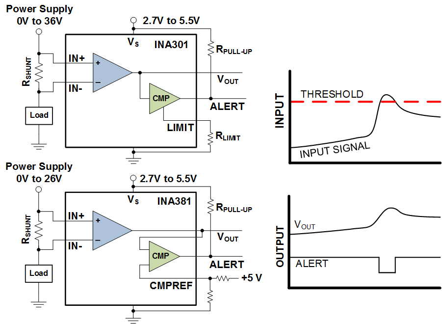
The INA301 and INA381 combines both the current sense amplifier (providing a voltage output signal proportional to the measured input current) and an on-board comparator (for over-current detection) into one device as shown in Figure 1-4.
 Figure 1-4 Integrated Over-Current
Detection with INA301 and INA381
 With both the current information and an out-of-range indicator the system may utilize multiple monitoring and protection schemes based on the operating conditions. One scheme used with this device is to initially monitor only the alert indicator as a fault indicator. Once an out-of-range condition is detected and the alert pin is asserted, the system then begins actively monitoring the analog output voltage signal allowing the system to respond accordingly. The system response typically will be to reduce system performance level, shut down entirely or to continue monitoring to determine if the excursion continues to become a more significant system concern. Having both the proportional output voltage as well as the on-board over-current detection function allows the system to only actively monitor the current information when necessary optimizing system resources. The INA381 is similar in function to the INA301 except both inputs to the over-current comparator are directly accessible for greater flexibility when setting the over current trip threshold.
The INA301 provides a combination of performance capability in addition to the integration of both the current sensing amplifier as well as on-board comparator. The INA301 amplifier's has a small signal bandwidth of 450 kHz at a fixed gain of 100 (gains of 20 and 50 are also available) and a maximum input offset voltage of 35 µV. In addition to the maximum gain error specification of 0.2%, the amplifier's ability to detect the out-of-range condition is fast. The INA301 is able to achieve accurate input measurements and quickly respond to over-current events with a response time including the input signal measurement, comparison to the user-selected alert threshold, and assertion of the comparators output in less than 1µs.
Alternate Device Recommendations
For applications needing to monitor current on voltage rails that are higher than the INA301's range of 36V with the on-board over-current detection, use the INA200. The INA180 is a current sense amplifier that is commonly used in the discrete over-current detection circuit using an external comparator. The INA381 provides a cost effective solution for over current detection in applications that feature a common mode range less than 26 V. For applications requiring monitoring of a second fault threshold level, the INA302 features an additional out-of-range comparator with dedicated adjustable threshold level.
| Device | Optimized Parameter | Performance Trade-off |
|---|---|---|
| INA180 | Package: SC70-5, SOT23-5 | Reduced bandwidth, analog output only |
| INA381 | Cost, Flexibility | Reduced bandwidth, Common mode voltage |
| INA200 | Common-mode Voltage Range: -16 V to +80 V | Reduced accuracy |
| INA302 | Two Independent Alert Comparators | Larger Package: TSSOP-14 |
Related Documentation
- Low-Drift, Low-Side Current Measurements for Three Phase Systems
- High-Side Motor Current Monitoring for Over-Current Protection
- Integrating The Current Sensing Signal Path
- Monitoring Current for Multiple Out-of-Range Conditions
- Safety and Protection for Discrete Digital Outputs in a PLC System Using Current Sense Amplifiers