SBAA464 September 2020 AMC3302
Introduction
Several industrial and automotive applications such as on board chargers, solar inverters, DC charging (pile) stations, power conversion systems, and motor drives require isolation to protect the digital circuitry from the high-voltage circuit performing a measurement. Two ways to accomplish the isolated current sensing for these applications are isolated shunt based sensing and magnetic (Hall or flux-gate) based sensing. This document compares Texas Instruments AMC3302 a single-supply, isolated amplifier to a popular closed-loop current sensor (CLCS).
Technologies Overview
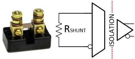 Figure 1-1 Isolated Shunt Based Current
Sensing. Isolated shunt based current sensing relies on measuring a voltage across a
precise in-line resistor, known as a shunt resistor.
 The shunt resistance must be very accurate in order to produce the expected voltage for the supplied current, as any variation in expected resistance will contribute directly to a gain error. The benefit of shunt based current sensing is that it allows for industry leading accuracy, immunity to magnetic interference, scalability and small size.
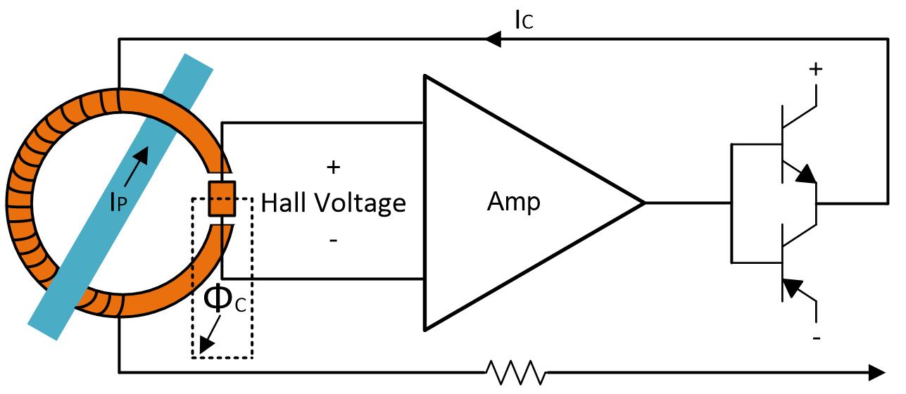 Figure 1-2 Hall Based Closed-Loop
Sensor. CLCS uses a magnetic core to sense the magnetic field created by the current
passing through the primary conductor. The magnetic field sensing element
included in the CLCS is used to provide a compensation current that is applied
to the magnetic core. This compensation current creates a flux that is equal in
magnitude, but in the opposite direction of the flux created by the primary
conductor; producing a zero-flux measurement. Magnetic based current sensing is
vulnerable to magnetic interference which can affect the offset and linearity
performance of the device.
Figure 1-2 Hall Based Closed-Loop
Sensor. CLCS uses a magnetic core to sense the magnetic field created by the current
passing through the primary conductor. The magnetic field sensing element
included in the CLCS is used to provide a compensation current that is applied
to the magnetic core. This compensation current creates a flux that is equal in
magnitude, but in the opposite direction of the flux created by the primary
conductor; producing a zero-flux measurement. Magnetic based current sensing is
vulnerable to magnetic interference which can affect the offset and linearity
performance of the device.Additional information comparing the two technologies can be found here.
Test Setup
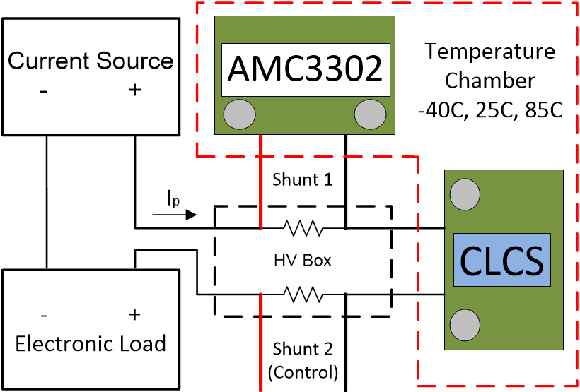 Figure 1-3 AMC3302 Circuit and CLCS Test
Setup Block Diagram. A test setup was created in order to directly compare the performance of these
two technologies. A DC current source, electronic load and digital multi-meters
were used to capture data for a +/-85A primary current sweep at three different
temperatures; -40C, 25C and 85C. All measurements were automated according to
IEEE488.
 Please note that the 500µΩ Shunt 1 used for the AMC3302 circuit measurement and 500µΩ Shunt 2 used for the control measurement were not subjected to changes in ambient temperature, therefor the shunt temperature drift error is not included in this analysis. Both shunts are rated for ±0.25% tolerance, ±15ppm/°C temperature coefficient and 20W power dissipation.
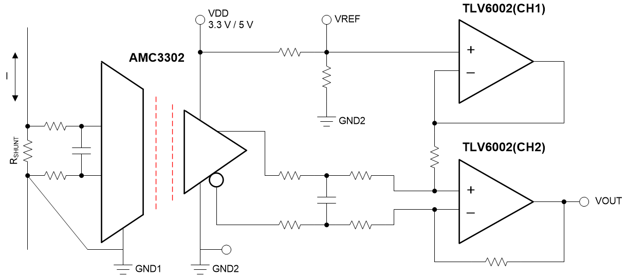 Figure 1-4 AMC3302 Circuit
Diagram.
The circuit diagram below shows the AMC3302 and TLV6002 circuit used for the accuracy comparison. Channel 1 of the TLV6002 was used to buffer a reference voltage generated via resistor divider while the differential output of the AMC3302 was converted from differential to single-ended via channel 2. Thus the AMC3302 circuit has an identical interface as the CLCS; VDD, GND, VREF and VOUT.
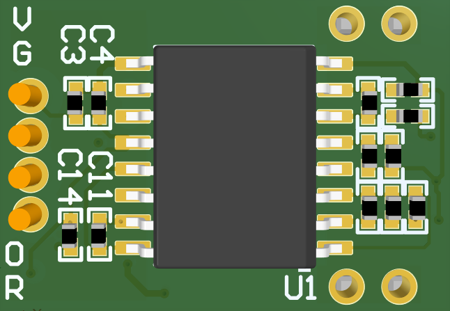 Figure 1-5 AMC3302 Circuit Printed
Circuit Board.
Below is the AMC3302 Printed Circuit Board (PCB). The PCB was designed such that the AMC3302 circuit fits within the same x, y footprint as the CLCS, 13.4mm x 21.9mm. The AMC3302 PCB is much smaller in terms of height; 2.6mm compared to 16mm for the CLCS, a reduction in height of 84%.
Accuracy Comparison
Figure 6. shows the accuracy results for the +/-85A primary current sweep over temperature in terms of error as a percentage of full-scale output after a 25C offset calibration. The AMC3302 circuit results are shown in shades of red and the CLCS in blue. The AMC3302 circuit is very accurate over the full current and temperature range without gain calibration, better than 0.1%. The CLCS shows worse gain error drift and linearity performance compared to the AMC3302 circuit, resulting in an overall error greater than 0.5%. The AMC3302 circuit offers an accuracy improvement of more than 5x compared to the CLCS over the full current and temperature range.
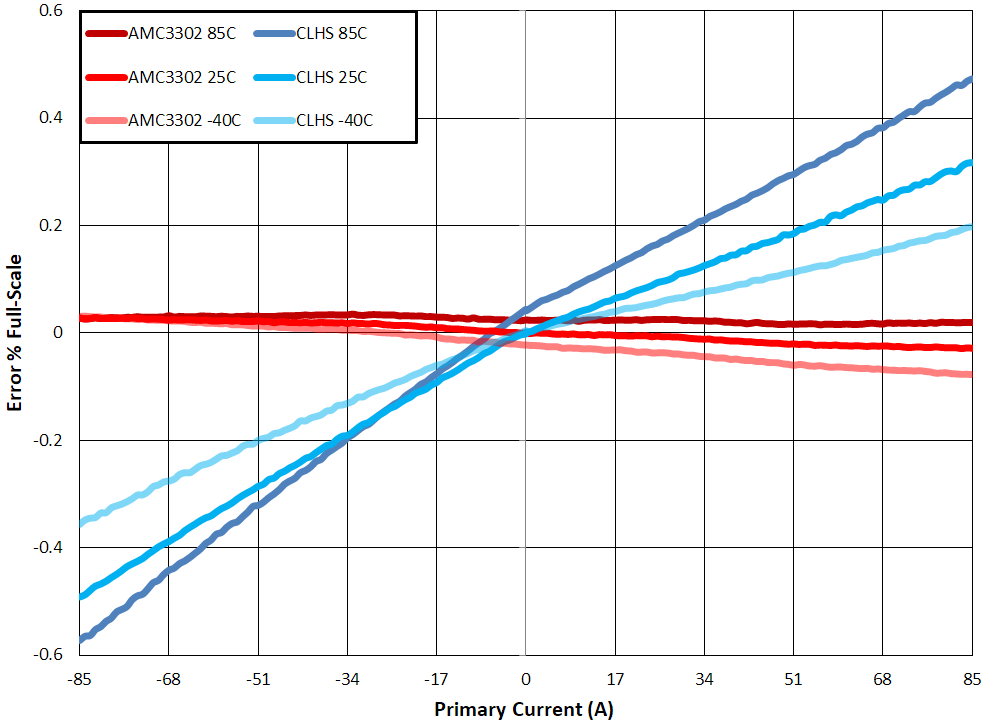 Figure 1-6 Accuracy Comparison for
AMC3302 Circuit and Closed-loop Current Sensor After Offset Calibration.
 Below shows an accuracy comparison table of absolute maximum error.
|
Temperature |
-40C |
25C |
85C |
|---|---|---|---|
|
AMC3302 Circuit |
-0.077% |
-0.029% |
0.035% |
|
CLCS |
-0.356% |
-0.492% |
-0.573% |
Conclusion
The table below summarizes the comparison of the AMC3302 circuit and the CLCS. For systems requiring industry leading accuracy, the AMC3302 circuit shows a clear advantage compared to the CLCS. The size of the AMC3302 circuit used for this comparison is equal size in terms of x and y dimensions, while showing a clear advantage in terms of height, z. The AMC3302 circuit also offers immunity to magnetic interference, as well as scalability.
|
AMC3302 Circuit |
CLCS |
|
|---|---|---|
|
Accuracy |
++ |
+ |
|
Size |
+ |
- |
|
Magnetic Immunity |
++ |
-- |
|
Scalability |
++ |
- |
|
Ease of Design |
+ |
++ |