SBVS171F December 2011 – October 2015 TPS7A16
PRODUCTION DATA.
- 1 Features
- 2 Applications
- 3 Description
- 4 Revision History
- 5 Pin Configuration and Functions
- 6 Specifications
- 7 Detailed Description
- 8 Application and Implementation
- 9 Power Supply Recommendations
- 10Layout
- 11Device and Documentation Support
- 12Mechanical, Packaging, and Orderable Information
パッケージ・オプション
メカニカル・データ(パッケージ|ピン)
サーマルパッド・メカニカル・データ
発注情報
1 Features
- Wide Input Voltage Range: 3 V to 60 V
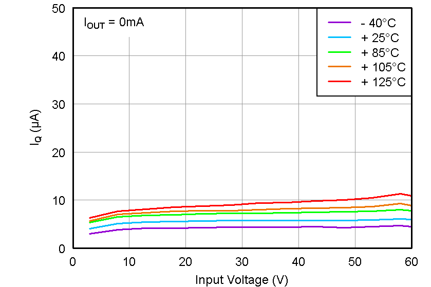
- Ultralow Quiescent Current: 5 µA
- Quiescent Current at Shutdown: 1 µA
- Output Current: 100 mA
- Low Dropout Voltage: 60 mV at 20 mA
- Accuracy: 2%
- Available in:
- Fixed Output Voltage: 3.3 V, 5 V
- Adjustable Version from 1.2 V to 18.5 V
- Power-Good With Programmable Delay
- Current Limit and Thermal Shutdown Protections
- Stable with Ceramic Output Capacitors:
≥ 2.2 µF - Packages: High Thermal Performance MSOP-8 and SON-8 PowerPAD™
- Operating Temperature Range:
–40°C to 125°C
2 Applications
- Power Supplies for Notebook PCs, Digital TVs, and Private LAN Systems
- High Cell-Count Battery Packs for Power Tools and other Battery-Powered Microprocessor and Microcontroller Systems
- Car Audio, Navigation, Infotainment, and Other Automotive Systems
- Smoke and CO2 Detectors and Battery-Powered Alarm and Security Systems
3 Description
The TPS7A16 family of ultralow power, low-dropout (LDO) voltage regulators offers the benefits of ultra-low quiescent current, high input voltage and miniaturized, high thermal-performance packaging.
The TPS7A16 family is designed for continuous or sporadic (power backup) battery-powered applications where ultralow quiescent current is critical to extending system battery life.
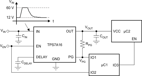
The TPS7A16 family offers an enable pin (EN) compatible with standard CMOS logic and an integrated open drain active-high power good output (PG) with a user-programmable delay. These pins are intended for use in microcontroller-based, battery-powered applications where power-rail sequencing is required.
In addition, the TPS7A16 is ideal for generating a low-voltage supply from multicell solutions ranging from high cell-count power-tool packs to automotive applications; not only can this device supply a well-regulated voltage rail, but it can also withstand and maintain regulation during voltage transients. These features translate to simpler and more cost-effective, electrical surge-protection circuitry.
Device Information(1)
| PART NUMBER | PACKAGE | BODY SIZE (NOM) |
|---|---|---|
| TPS7A16 | HVSSOP (8) | 3.00 mm × 3.00 mm |
| VSON (8) | 3.00 mm × 3.00 mm |
- For all available packages, see the package option addendum at the end of the data sheet.
Typical Application Schematic

Quiescent Current vs Input Voltage
