SLVSA72E April 2010 – October 2015 DRV8813
PRODUCTION DATA.
- 1 Features
- 2 Applications
- 3 Description
- 4 Revision History
- 5 Pin Configuration and Functions
- 6 Specifications
- 7 Detailed Description
- 8 Application and Implementation
- 9 Power Supply Recommendations
- 10Layout
- 11Device and Documentation Support
- 12Mechanical, Packaging, and Orderable Information
Package Options
Mechanical Data (Package|Pins)
- PWP|28
Thermal pad, mechanical data (Package|Pins)
- PWP|28
Orderable Information
1 Features
- 8.2-V to 45-V Operating Supply Voltage Range
- 2.5-A Maximum Drive Current at 24 V and
TA = 25°C - Dual H-Bridge Current Control Motor Driver
- Drive a Bipolar Stepper or Two DC Motors
- Four Level Winding Current Control
- Multiple Decay Modes
- Mixed Decay
- Slow Decay
- Fast Decay
- Industry Standard Parallel Digital Control Interface
- Low Current Sleep Mode
- Built In 3.3-V Reference Output
- Small Package and Footprint
- Protection Features
- Overcurrent Protection (OCP)
- Thermal Shutdown (TSD)
- VM Undervoltage Lockout (UVLO)
- Fault Condition Indication Pin (nFAULT)
2 Applications
3 Description
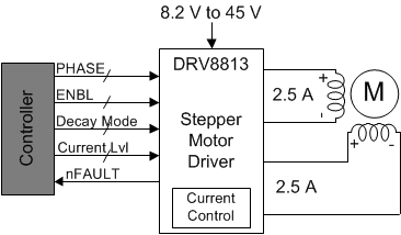
The DRV8813 provides an integrated motor driver solution for printers, scanners, and other automated equipment applications. The device has two H-bridge drivers, and can drive a bipolar stepper motor or two DC motors. The output driver block for each consists of N-channel power MOSFETs configured as full H-bridges to drive the motor windings. The DRV8813 can supply up to 2.5-A peak or 1.75-A RMS output current (with proper heatsinking at 24 V and 25°C).
A simple parallel digital control interface is compatible with industry-standard devices. Decay mode is programmable.
Internal shutdown functions are provided for overcurrent protection, short circuit protection, undervoltage lockout and overtemperature.
The DRV8813 is available in a 28-pin HTSSOP package with PowerPAD™ (Eco-friendly: RoHS & no Sb/Br).
Device Information(1)
| PART NUMBER | PACKAGE | BODY SIZE (NOM) |
|---|---|---|
| DRV8813 | HTSSOP (28) | 9.70 mm × 4.40 mm |
- For all available packages, see the orderable addendum at the end of the data sheet.
Simplified Schematic
