SLUSBN7D January 2014 – April 2017
PRODUCTION DATA.
- 1 Features
- 2 Applications
- 3 Description
- 4 Revision History
- 5 Device Comparison Table
- 6 Pin Configuration and Functions
-
7 Specifications
- 7.1 Absolute Maximum Ratings
- 7.2 ESD Ratings
- 7.3 Recommended Operating Conditions
- 7.4 Thermal Information
- 7.5 Supply Current
- 7.6 Digital Input and Output DC Characteristics
- 7.7 LDO Regulator, Wake-Up, and Auto-Shutdown DC Characteristics
- 7.8 ADC (Temperature and Cell Measurement) Characteristics
- 7.9 Integrating ADC (Coulomb Counter) Characteristics
- 7.10 I2C-Compatible Interface Communication Timing Characteristics
- 7.11 Typical Characteristics
- 8 Detailed Description
- 9 Applications and Implementation
- 10Power Supply Recommendation
- 11Layout
- 12Device and Documentation Support
- 13Mechanical, Packaging, and Orderable Information
Package Options
Mechanical Data (Package|Pins)
- DRZ|12
Thermal pad, mechanical data (Package|Pins)
Orderable Information
1 Features
- Single-Cell Li-Ion Battery Fuel Gauge
- Resides in Battery Pack
- Low-Value External Sense Resistor
(10 mΩ Typical) - One Time Programmable (OTP) Configuration Non-Volatile Memory (NVM)
- Powered Directly from Battery with Integrated LDO
- 400-kHz I2C™ Serial Interface
- Internal Temperature Sensor or
Host-reported Temperature
- Battery Fuel Gauging Based on Patented Impedance
Track™ Technology
- Reports Remaining Capacity and State of Charge (SOC) with Smoothing Filter
- Automatically Adjusts for Battery Aging, Self-discharge, Temperature, and Rate Changes
- Battery State of Health (Aging) Estimation
2 Applications
- Smartphones, Feature Phones, and Tablets
- Digital Still and Video Cameras
- Handheld Terminals
- MP3 or Multimedia Players
3 Description
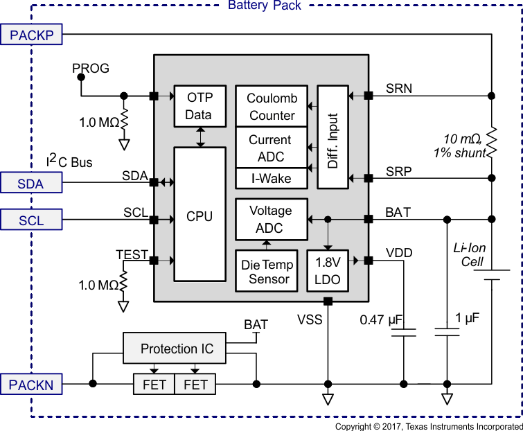
The Texas Instruments bq27411-G1 device is a battery fuel gauging solution for single-cell Li-Ion battery packs. The device requires minimal configuration and uses One Time Programmable (OTP) Non-Volatile Memory (NVM) to avoid an initialization download by the system processor.
The fuel gauge uses the patented Impedance Track™ algorithm for fuel gauging, and provides information such as remaining battery capacity (mAh), state-of-charge (%), and battery voltage (mV).
The small, 12-pin, 2.50 mm × 4.00 mm, Small Outline No-Lead (SON) package is ideal for space-constrained applications.
Device Information(1)
| PART NUMBER | PACKAGE | BODY SIZE (NOM) |
|---|---|---|
| bq27411-G1 | VSON (12) | 2.50 mm x 4.00 mm |
- For all available packages, see the orderable addendum at the end of the data sheet.
