SLLS684I July 2006 – March 2016 TPD2E001
PRODUCTION DATA.
- 1 Features
- 2 Applications
- 3 Description
- 4 Revision History
- 5 Pin Configuration and Functions
- 6 Specifications
- 7 Detailed Description
- 8 Application and Implementation
- 9 Power Supply Recommendations
- 10Layout
- 11Device and Documentation Support
- 12Mechanical, Packaging, and Orderable Information
Package Options
Mechanical Data (Package|Pins)
Thermal pad, mechanical data (Package|Pins)
Orderable Information
1 Features
-
IEC 61000-4-2 ESD Protection (Level 4)
- ±8-kV Contact Discharge
- ±15-kV Air-Gap Discharge
- IO Capacitance: 1.5 pF (Typ)
- Low Leakage Current: 1 nA (Maximum)
- Low Supply Current: 1 nA
- 0.9 V to 5.5 V Supply-Voltage Range
- Space-Saving DRL, DRY, and QFN Package Options
- Alternate 3, 4, 6-Channel options Available: TPD3E001, TPD4E001, TPD6E001
2 Applications
3 Description
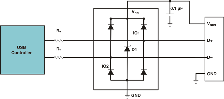
The TPD2E001 is a two-channel Transient Voltage Suppressor (TVS) based Electrostatic Discharge (ESD) protection diode array. The TPD2E001 is rated to dissipate ESD strikes at the maximum level specified in the IEC 61000-4-2 Level 4 international standard.
The DRS package (3.00 mm x 3.00 mm) is also available as a non-magnetic package for medical imaging applications.
See also TPD2E2U06DRLR which is p2p compatible to TPD2E001DRLR and offers higher IEC ESD Protection, lower clamping voltage, and eliminates the input capacitor requirement.
Device Information(1)
| PART NUMBER | PACKAGE | BODY SIZE (NOM) |
|---|---|---|
| TPD2E001 | SOT (5) | 1.60 mm x 1.20 mm |
| WSON (6) | 3.00 mm x 3.00 mm | |
| USON (6) | 1.45 mm x 1.00 mm | |
| SOP (4) | 2.90 mm x 1.30 mm |
- For all available packages, see the orderable addendum at the end of the data sheet.
Application Schematic
