SLVSBA5D October 2012 – April 2016 DRV8313
PRODUCTION DATA.
- 1 Features
- 2 Applications
- 3 Description
- 4 Revision History
- 5 Pin Configuration and Functions
- 6 Specifications
- 7 Detailed Description
- 8 Application and Implementation
- 9 Power Supply Recommendations
- 10Layout
- 11Device and Documentation Support
- 12Mechanical, Packaging, and Orderable Information
Package Options
Mechanical Data (Package|Pins)
Thermal pad, mechanical data (Package|Pins)
Orderable Information
1 Features
- Triple 1/2-H Bridge Driver IC
- 3-Phase brushless DC Motors
- Solenoid and Brushed DC Motors
- High Current-Drive Capability: 2.5-A Peak
- Low MOSFET ON-Resistance
- Independent 1/2-H-Bridge Control
- Uncommitted Comparator Can Be Used for Current Limit or Other Functions
- Built-In 3.3-V 10-mA LDO Regulator
- 8-V to 60-V Operating Supply-Voltage Range
- Sleep Mode for Standby Operation
- Small Package and Footprint
- 28-Pin HTSSOP (PowerPAD™ Package)
- 36-Pin VQFN
2 Applications
- Camera Gimbals
- HVAC Motors
- Office Automation Machines
- Factory Automation and Robotics
3 Description
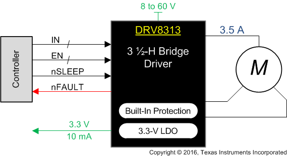
The DRV8313 provides three individually controllable half-H-bridge drivers. The device is intended to drive a three-phase brushless-DC motor, although it can also be used to drive solenoids or other loads. Each output driver channel consists of N-channel power MOSFETs configured in a 1/2-H-bridge configuration. Each 1/2-H-bridge driver has a dedicated ground terminal, which allows independent external current sensing.
An uncommitted comparator is integrated into the DRV8313, which allows for the construction of current-limit circuitry or other functions.
Internal protection functions are provided for undervoltage, charge pump faults, overcurrent, short circuits, and overtemperature. Fault conditions are indicated by the nFAULT pin.
Device Information(1)
| PART NUMBER | PACKAGE | BODY SIZE (NOM) |
|---|---|---|
| DRV8313 | HTSSOP (28) | 9.70 mm × 4.40 mm |
| VQFN (36) | 6.00 mm × 6.00 mm |
- For all available packages, see the orderable addendum at the end of the data sheet.
Simplified Schematic
