SLASED6D April 2016 – December 2017 DAC60004 , DAC70004 , DAC80004
PRODUCTION DATA.
- 1 Features
- 2 Applications
- 3 Description
- 4 Revision History
- 5 Device Comparison Table
- 6 Pin Configuration and Functions
- 7 Specifications
-
8 Detailed Description
- 8.1 Overview
- 8.2 Functional Block Diagram
- 8.3 Feature Description
- 8.4 Device Functional Modes
- 9 Application and Implementation
- 10Power Supply Recommendations
- 11Layout
- 12Device and Documentation Support
- 13Mechanical, Packaging, and Orderable Information
Package Options
Mechanical Data (Package|Pins)
Thermal pad, mechanical data (Package|Pins)
- DMD|14
Orderable Information
1 Features
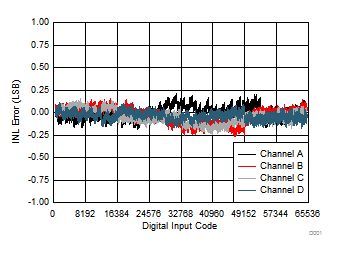
- True 16-Bit Performance: 1 LSB INL/DNL (Max)
- Ultra Low Glitch Energy: 1 nV-s
- Wide Power-Supply Range: 2.7 V to 5.5 V
- Output Buffer with Rail-to-Rail Operation
- Current Consumption: 1 mA/Channel
- 50-MHz, 4- or 3-Wire SPI Compatible Interface
- SDO Pin for Readback and Daisy Chain
- Power-On Reset to Zero or Mid Scale
- Temperature Range: –40°C to +125°C
- Multiple Packages:
- Tiny 14-Pin VSON
- 14-Pin TSSOP
2 Applications
- Portable Instrumentation
- PLC Analog Output Module (4-20 mA)
- Closed-Loop Servo Control
- Data Acquisition Systems
3 Description
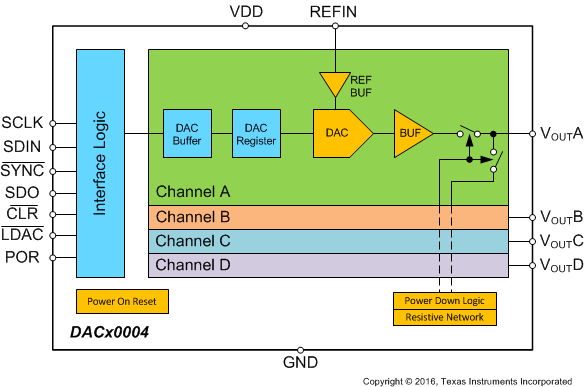
The DAC80004/70004/60004 (DACx0004) are highly accurate, low-power, voltage-output, quad-channel, 16-, 14-, 12-bit digital-to-analog converters (DACs) respectively. The DACx0004 devices are ensured monotonic by design and offer excellent linearity of less than 1 LSB (Max). The reference input of the DAC is buffered internally using a dedicated reference buffer.
The DACx0004 devices incorporate a power-on-reset circuit that ensures the DAC output powers up at zero scale or mid scale depending on status of the POR pin and remains in this state until a valid code is written to the device. These devices consume very low current of 1 mA/channel making them ideal for portable, battery-operated equipment. These devices also contain a power-down feature that reduces current consumption to typically 3 µA at 5 V.
The DACx0004 devices use a versatile 4- or 3-wire serial interface that operates at clock rates up to 50 MHz. The DACx0004 devices also include a SDO pin to daisy chain multiple devices. The interface is compatible with standard SPI™, QSPI™, Microwire, and digital signal processor (DSP) interfaces. The DACx0004 devices are offered in easy-to-assemble 14-pin TSSOP packages or an ultra small 14-pin VSON package and are fully specified over the extended industrial temperature range of –40°C to 125°C.
Device Information(1)
| PART NUMBER | PACKAGE | BODY SIZE (NOM) |
|---|---|---|
| DACx0004 | VSON (14) | 3.00 mm x 4.00 mm |
| DACx0004 | TSSOP (14) | 5.00 mm x 4.40 mm |
- For all available packages, see the orderable addendum at the end of the data sheet.
DACx0004 Block Diagram

Linearity Error vs Digital Input Code
