SLUSC27C April 2015 – March 2017
PRODUCTION DATA.
- 1 Features
- 2 Applications
- 3 Description
- 4 Revision History
- 5 Pin Configuration and Functions
- 6 Specifications
-
7 Detailed Description
- 7.1 Overview
- 7.2 Functional Block Diagram
- 7.3 Feature Description
- 7.4 Device Functional Modes
- 7.5 Programming
- 7.6
Register Maps
- 7.6.1 Battery-Charger Commands
- 7.6.2 Setting Charger Options
- 7.6.3 ChargeOption1 Register
- 7.6.4 ChargeOption2 Register
- 7.6.5 ChargeOption3 Register
- 7.6.6 ProchotOption0 Register
- 7.6.7 ProchotOption1 Register
- 7.6.8 ProchotStatus Register
- 7.6.9 Setting the Charge Current
- 7.6.10 Setting the Charge Voltage
- 7.6.11 Setting Input Current
- 7.6.12 Setting the Discharge Current
- 8 Application and Implementation
- 9 Power Supply Recommendations
- 10Layout
- 11Device and Documentation Support
- 12Mechanical, Packaging, and Orderable Information
Package Options
Mechanical Data (Package|Pins)
- RUY|28
Thermal pad, mechanical data (Package|Pins)
Orderable Information
1 Features
- Industrial Innovative Charge Controller With Hybrid Power Boost Mode
- High Accuracy Power and Current Monitoring for CPU Throttling
- Comprehensive PROCHOT Profile
- ± 2% Current Monitor Accuracy
- ± 5% System Power Monitor Accuracy (PMON)
- Automatic NMOS Power Source Selection from Adapter or Battery
- ACFET Fast Turn on in 100 µs
- Programmable Input Current, Charge Voltage, Charge and Discharge Current Limit
- ±0.4% Charge Voltage (16-mV step)
- ±2% Input Current (128-mA/step)
- ±2% Charge Current (64-mA/step)
- ±2% Discharge Current (512-mA/step)
- High Integration
- Battery LEARN Function
- Battery Present Monitor
- Boost Mode Indicator
- Loop Compensation
- BTST Diode
- Enhanced Safety Features for Overvoltage Protection, Overcurrent Protection, Battery, Inductor, and MOSFET Short-Circuit Protection
- Switching Frequency: 600 kHz, 800 kHz, and
1 MHz - Realtime System Control on ILIM Pin to Limit Charge and Discharge Current
- 0.65 mA Adapter Standby Quiescent Current for Energy Star
2 Applications
- Notebook, Ultrabook, Detachable, and Tablet PC
- Handheld Terminal
- Industrial and Medical Equipment
- Portable Equipment
3 Description
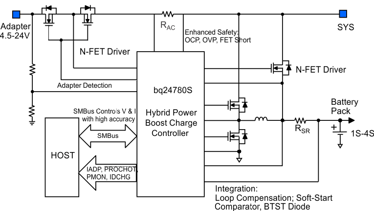
The bq24780S device is a high-efficiency, synchronous battery charger, offering low component count for space-constrained, multi-chemistry battery charging applications.
The bq24780S device supports hybrid power boost mode (previously called "turbo boost mode"). It allows battery discharge energy to system when system power demand is temporarily higher than adapter maximum power level. Therefore, adapter does not crash.
The bq24780S device uses two charge pumps to separately drive N-channel MOSFETs (ACFET, RBFET, and BATFET) for automatic system power source selection.
Through SMBus, system power management microcontroller programs input current, charge current, discharge current, and charge voltage DACs with high regulation accuracies.
The bq24780S device monitors adapter current (IADP), battery discharge current (IDCHG), and system power (PMON) for host to throttle back CPU speed or reduce system power when needed.
The bq24780S device charges 1-, 2-, 3-, or 4-series Li+ cells.
Device Information(1)
| PART NUMBER | PACKAGE | BODY SIZE (NOM) |
|---|---|---|
| bq24780S | WQFN (28) | 4.00 × 4.00 mm2 |
- For all available packages, see the orderable addendum at the end of the data sheet.

4 Revision History
Changes from B Revision (April 2015) to C Revision
- Full data sheet to product folderGo
Changes from A Revision (April 2015) to B Revision
- Changed the Description for pin 22 (GND) in the Pin Functions tableGo
- Changed the Thermal Pad to PowerPAD in the Pin Functions tableGo
- Changed 16X to 20X on the SRP and SRN pins of the Functional Block Diagram Go
- Changed C4 From: 0.01 μF To: 0.1 μF in Figure 17 Go
Changes from * Revision (April 2015) to A Revision
- Changed V(ACOC) in the Electrical Characteristics, MIN From: 190% To: 180%, MAX From: 215% To: 220% Go
- Changed "ChargeOption() bit [0] = 0" To: REG0x12[0] in Enable and Disable ChargingGo
- Changed " (REG0x12[1])" To: (REG0x12[0]=1) in Enable and Disable ChargingGo
- Changed " REG0x12" To: "REG0x12[0]" in Battery ChargingGo
- Changed Bit [10:9] in Table 9 From: 11: 8 ms To: 11: 800 µs Go
- Added sentence to Bit [7:6] in Table 9 " If REG0x15() is programmed..."Go
- Changed text in Bit [5] of Table 9 From: "write 0x3C[2] = 1." To: "write 0x3C[2] = 0."Go
- Deleted text from Bit [5] of Table 9 "This function is not available in 1s battery."Go